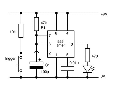
In the vast landscape of electrical schematics, timer symbols act as silent guardians of time, controlling the dance of electricity within circuits. They're precise visual codes telling a story of delays, pulses, and rhythmic activations.
What Is Timer Symbol Electrical

In electrical circuit diagrams, a timer is represented by a specific symbol that indicates the presence of a timing device or function within the circuit. The symbol for a timer may vary slightly depending on the type of timer being used, such as a simple on/off delay timer, a programmable timer, or a specialized timing relay. Here are some common timer symbols you may encounter in electrical schematics:
-
Standard Timer Symbol: The standard symbol for a timer resembles a square or rectangular box with various internal elements representing the timing function. The symbol may include control terminals and timing adjustment features depending on the complexity of the timer.
-
On-Delay Timer Symbol: An on-delay timer is typically represented by a box with a specified delay value and an arrow or line indicating the timing sequence. The symbol may also include terminals for connection to the circuit.
-
Off-Delay Timer Symbol: An off-delay timer symbol is similar to the on-delay timer symbol but with distinct features signifying an off-delay function, where the output remains active for a set time after the input signal is removed.
-
Programmable Timer Symbol: A programmable timer symbol may include additional elements such as a display screen, control buttons, and programming interfaces to enable users to set custom timing parameters. The symbol may also depict different operational modes and timing options.
-
Timing Relay Symbol: In the case of a timing relay, the symbol often combines elements of a relay (switching function) with timing components. It may include contacts, coils, and timer settings within the same symbol to represent the integrated timing and switching functionality.
-
Multifunction Timer Symbol: For timers with multiple timing modes or functions, the symbol can be more intricate, incorporating various timing elements, mode selectors, and feedback indicators to illustrate the timer's versatile features.
Understanding these symbols is essential for interpreting circuit diagrams accurately and identifying the presence of timers or timing functions within electrical systems. By recognizing the specific timer symbols and their associated functions, technicians, engineers, and electricians can effectively analyze and troubleshoot circuits that incorporate timing devices for control, automation, or sequencing purposes.
The Applications Of Electrical Timer Symbols
Electrical timer symbols are essential components in circuit diagrams and schematics, representing various timing devices used in control, automation, and sequencing applications. Here are some common applications of electrical timer symbols in various electrical and electronic systems:
- Industrial Automation:
- Sequence Control: Electrical timers are widely used in industrial automation for sequencing operations, controlling processes, and ensuring proper timing between different stages of a manufacturing or production line.
- Motor Control:
- Motor Starters: Timer symbols are used in motor control circuits to implement time-delayed start or stop functions, prevent rapid cycling of motors, and provide overload protection.
- Lighting Control:
- Lighting Timers: Electrical timers are employed in lighting control systems for automatic switching of lights based on preset schedules, occupancy detection, or daylight conditions.
- HVAC Systems:
- Thermostat Timers: Timers in HVAC (Heating, Ventilation, and Air Conditioning) systems control the operation of heaters, air conditioners, and fans to optimize energy efficiency and maintain comfortable indoor conditions.
- Pump Control:
- Pump Sequencing: Timer symbols are used in pump control applications to sequence the operation of multiple pumps, prevent simultaneous starting, and manage pump run times for optimal system performance.
- Security Systems:
- Access Control: Electrical timers play a role in access control systems by regulating door locks, gates, and security barriers on a timed basis for entry/exit control and security enforcement.
- Traffic Signal Control:
- Traffic Light Sequencing: Timer symbols are utilized in traffic signal control systems to manage the sequencing of traffic lights at intersections, pedestrian crossings, and other road junctions.
- Appliance Control:
- Appliance Timers: Timers in appliances such as washing machines, ovens, coffee makers, and programmable thermostats enable users to set specific start or stop times, duration, and operating cycles.
- Irrigation Systems:
- Timer-Controlled Irrigation: Electrical timers regulate the timing and duration of irrigation systems in agriculture, landscaping, and gardening applications to ensure efficient water usage and proper plant maintenance.
- Power Management:
- Power Scheduling: Timers are used in power management systems to schedule equipment operation, energy consumption peaks, and electricity demand to optimize energy usage and reduce costs.
By integrating electrical timer symbols into circuit designs, engineers, electricians, and system integrators can implement precise timing functions, automation sequences, and control strategies in a wide range of applications across industries, enhancing efficiency, safety, and operational reliability in various electrical and electronic systems.
The Advantages Of Electrical Timer Symbols
Electrical timer symbols play a crucial role in circuit diagram representation, offering several advantages in electrical engineering, design, and troubleshooting. Here are some key advantages of using electrical timer symbols in various applications:
-
Clarity and Communication:
- Electrical timer symbols provide a standardized and universally recognized representation of timing devices in circuit diagrams, ensuring clear communication between design engineers, electricians, technicians, and other stakeholders involved in the project.
-
Schematic Understanding:
- By incorporating timer symbols in circuit diagrams, professionals can easily identify the presence of timing functions, sequences, and delays within the electrical system, facilitating better comprehension of the circuit's operation and functionality.
-
Design Precision:
- Using electrical timer symbols enables precise and accurate circuit design by specifying the type, function, and location of timing devices in the schematic, ensuring that timing requirements are appropriately met and integrated into the system design.
-
Troubleshooting and Maintenance:
- Timer symbols aid in troubleshooting electrical circuits by helping technicians locate and diagnose issues related to timing functions, such as timing discrepancies, faults in timer circuits, or malfunctions in timing relays, leading to faster and more efficient repairs.
-
Customization and Flexibility:
- Electrical timer symbols offer flexibility in design by allowing engineers to select and incorporate different timer symbols based on the specific timing requirements of the application, enabling customization and adaptation to varied circuit configurations and functionalities.
-
System Integration:
- Timer symbols facilitate the integration of timing devices into complex electrical systems by providing a visual representation of how timers interact with other components, controls, and signals within the circuit, promoting seamless system integration and interoperability.
-
Documentation and Standards Compliance:
- Utilizing electrical timer symbols ensures that circuit diagrams adhere to industry standards and best practices for electrical documentation, enhancing consistency, compliance, and quality in design, installation, and maintenance processes.
-
Educational Tool:
- Timer symbols serve as educational tools for students, professionals, and enthusiasts in the field of electrical engineering by familiarizing them with common timing devices, functions, and symbols used in circuit diagrams, improving knowledge and expertise in circuit design and analysis.
-
Time-Saving Benefits:
- Incorporating timer symbols in circuit diagrams saves time during design and troubleshooting tasks by providing a visual shorthand for representing timing functions, logic sequences, and time-delay operations, streamlining the design process and accelerating problem-solving efforts.
In summary, electrical timer symbols offer numerous advantages in circuit design, communication, troubleshooting, and system integration by enhancing clarity, precision, customization, and efficiency in representing timing functions and devices within electrical schematics and diagrams.


