The LM393 is a dual voltage comparator integrated circuit (IC) that is commonly used in electronic circuits to compare voltages. The comparator's main function is to compare two voltage levels and output a digital signal based on which input is greater. It's often used in various applications like limit detection, level shifting, line following robots, and so on.

Here's a basic guide on how to use the LM393:
Pin Configuration:
The LM393 typically comes in an 8-pin dual in-line package (DIP). The pinout is as follows:
- VCC+ (Pin 8): Positive supply voltage.
- Input 1 (-) Inverting input (Pin 4): Non-inverting input of comparator 1.
- Input 1 (+) Non-inverting input (Pin 3): Inverting input of comparator 1.
- Output 1: Output of comparator 1.
- GND (Pin 1): Ground or 0V reference.
- Output 2: Output of comparator 2.
- Input 2 (-) Inverting input (Pin 5): Non-inverting input of comparator 2.
- Input 2 (+) Non-inverting input (Pin 6): Inverting input of comparator 2.
Basic Connections:
- Power Supply: Connect Pin 8 (VCC+) to a positive power supply, and Pin 4 (GND) to ground.
- Input Signals: The signals to be compared are applied to the non-inverting inputs (Pin 3 and Pin 6) and inverting inputs (Pin 4 and Pin 5).
- Output: The outputs (Pin 2 and Pin 7) produce a digital output based on the comparison result.
Example Circuit:
Suppose you have two voltage sources, V1 and V2, connected to the non-inverting and inverting inputs of the first comparator. You want to determine whether V1 is greater than V2. When V1 is greater than V2, the output of the first comparator is high. The same principle can be applied to the second comparator.
Here’s a simple connection to compare two voltages:
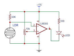
Output:
The output of the comparator (Pin 2 and Pin 7) will indicate which voltage is higher. If V1 is greater than V2, the output of Comparator 1 will be high and Comparator 2 will be low, and vice versa.
Please note that resistors are often used to limit the current going into the comparator’s inputs and can be selected based on the specific requirements of the application.
This is a basic setup to illustrate the working principle of the LM393. Actual circuitry and component choices can vary greatly depending on the specific requirements of your project. Always refer to the LM393 datasheet and/or application notes for precise details and application-specific understanding.

