The LM741 is a general-purpose operational amplifier (op-amp) integrated circuit widely used in analog electronic circuits. Developed by National Semiconductor (now part of Texas Instruments), the LM741 is a single operational amplifier IC with high gain, wide bandwidth, and versatile performance characteristics. Here are some key points about the LM741 op-amp:
Features of LM741 Op-Amp:
-
Single Operational Amplifier:
- The LM741 is a single op-amp IC with one amplifier circuit per chip.
-
General-Purpose Op-Amp:
- Designed for general-purpose analog applications, such as amplification, filtering, signal conditioning, and voltage comparison.
-
High Gain:
- The LM741 has a high open-loop voltage gain, typically around 100 dB, making it suitable for applications requiring signal amplification.
-
Wide Bandwidth:
- Offers a relatively wide bandwidth of several megahertz, allowing it to amplify signals across a range of frequencies.
-
Input Offset Voltage:
- The LM741 has a specified input offset voltage, which can affect the accuracy of the amplified signal. This can be compensated for in circuit design.
-
Low Input Bias Current:
- The op-amp has low input bias current, which minimizes the impact of input current on the circuit.
-
Low Offset Current:
- Features low offset current, which helps in reducing errors in signal amplification and processing.
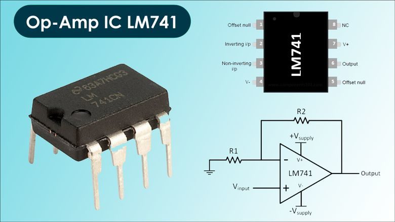
Pin Configuration of LM741 Op-Amp:
- The LM741 typically comes in an 8-pin DIP (Dual Inline Package) configuration, with the following pinout:
- Pin 1: Offset Null
- Pin 2: Inverting Input (-)
- Pin 3: Non-Inverting Input (+)
- Pin 4: V-
- Pin 5: Offset Null
- Pin 6: Output
- Pin 7: V+
- Pin 8: N/C (No Connection)
Applications of LM741 Op-Amp:
-
Inverting and Non-Inverting Amplifiers:
- Used in both inverting and non-inverting amplifier configurations for signal amplification.
-
Summing Amplifiers:
- Configured as summing amplifiers to combine multiple input signals with adjustable gains.
-
Active Filters:
- Employed in active filter circuits for signal filtering and frequency response shaping.
-
Voltage Followers:
- Used as voltage followers to buffer and isolate input and output signals.
-
Signal Processing Circuits:
- Integrated into various analog signal processing circuits due to its flexibility and performance.
-
Comparators:
- Configured as voltage comparators for comparing two input voltages and determining their relationship.
The LM741 op-amp is a fundamental building block in analog electronics, widely used in various applications for amplification, filtering, signal processing, and voltage comparison. Its versatility, robustness, and ease of use make it a popular choice for both educational purposes and professional electronics design.
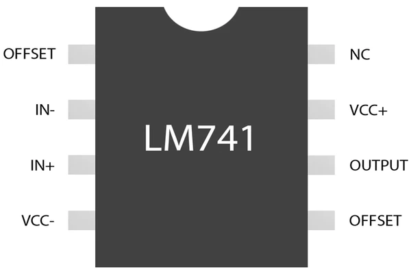
LM741 Pinout
The LM741 operational amplifier (op-amp) typically comes in an 8-pin Dual Inline Package (DIP) configuration. Below is the pinout for the LM741 op-amp IC:
LM741 Op-Amp Pinout:
- Offset Null: Connected to an external capacitor for compensating input offset voltage.
- Inverting Input (-): Inverting input terminal where the input signal is applied.
- Non-Inverting Input (+): Non-inverting input terminal for the input signal.
- V-: Negative power supply terminal.
- Offset Null: Connected to an external capacitor for compensating input offset voltage.
- Output: Output terminal where the amplified signal is available.
- V+: Positive power supply terminal.
- N/C (No Connection): This pin is not internally connected and is typically left unconnected.
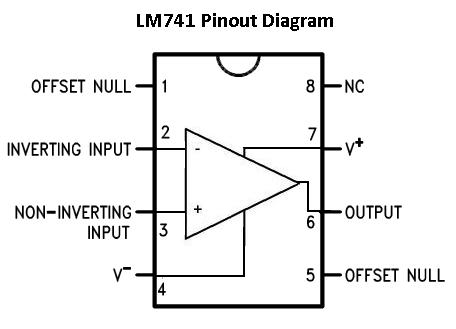
Summary of LM741 Pinout:
- Pin 1: Offset Null
- Pin 2: Inverting Input (-)
- Pin 3: Non-Inverting Input (+)
- Pin 4: V-
- Pin 5: Offset Null
- Pin 6: Output
- Pin 7: V+
- Pin 8: N/C (No Connection)
Pin Functions:
- Inverting Input (-): The inverting input terminal where the input signal is applied. It is typically marked with a negative sign.
- Non-Inverting Input (+): The non-inverting input terminal where the input signal is applied. It is typically marked with a positive sign.
- Output: The terminal where the amplified output signal is available.
- V+ and V-: The positive and negative power supply pins to provide the necessary voltage for the op-amp to operate.
Note:
- The Offset Null pins (1 and 5) are used for adjusting the offset voltage, but they are not always used in all applications.
When using the LM741 op-amp in a circuit, it's essential to pay attention to the pinout configuration to ensure proper connection and functionality. Each pin serves a specific purpose in the circuit, and following the correct pinout layout is crucial for the op-amp to perform as intended.
Feature & Specifications
LM741 Operational Amplifier: Features and Specifications
The LM741 is a widely-used general-purpose operational amplifier (op-amp) known for its versatility in various analog circuit applications. Below are the key features and specifications of the LM741 op-amp:
Features:
-
Single Operational Amplifier: The LM741 is a single-channel op-amp with one amplifier circuit in a single package.
-
Versatile Operation: Suitable for a wide range of analog applications including amplification, filtering, voltage following, and many others.
-
High Gain: Offers high voltage gain, making it suitable for amplifying weak signals.
-
Low Input Offset Voltage: Provides low input offset voltage for accurate signal processing.
-
Low Input Bias Current: Low input bias current reduces the loading effects on the input signal source.
-
Compensation for Capacitive Loads: Stable operation even with capacitive loads in the feedback loop.
Specifications:
-
Supply Voltage: Typically operates from dual power supplies ranging from ±5V to ±18V.
-
Input Offset Voltage: Typically in the range of 1 mV to 6 mV, impacting the accuracy of the output signal.
-
Input Offset Current: In the range of 0.5 nA to 30 nA, affecting the balance of the differential inputs.
-
Input Bias Current: Typically ranges from 80 nA to 500 nA, influencing the input signal requirements.
-
Gain Bandwidth Product: Around 1 MHz to 1.5 MHz, determining the bandwidth produced when amplifying signals.
-
Slew Rate: Approximately 0.5 V/µs to 0.6 V/µs, affecting the speed at which the output voltage changes in response to an input step change.
-
Common-Mode Rejection Ratio (CMRR): Often greater than 70 dB, indicating the op-amp's ability to reject common-mode signals.
-
Open-Loop Gain: Typically around 100 dB, showing the amplification capability when operating in an open-loop configuration.
-
Operating Temperature: Can typically operate in the temperature range from 0°C to 70°C.
Applications:
- The LM741 is commonly used in audio amplifiers, signal conditioning circuits, active filters, voltage followers, integrators, differentiators, and many other analog circuit applications.
Note:
- The specifications mentioned above are approximate values and may vary based on manufacturing variations and operating conditions.
The LM741 operational amplifier's features and specifications make it a versatile component for designing various analog circuits, offering high gain, low input offset voltage, and stable operation in different applications requiring signal processing, amplification, and filtering.
LM741 Circuit
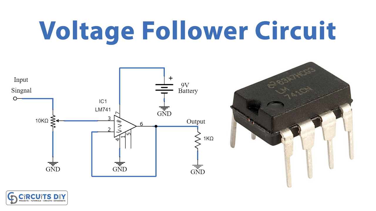
The LM741 operational amplifier (op-amp) is commonly used in a wide range of analog circuit applications due to its versatility and performance characteristics. One of the most basic and fundamental circuits utilizing the LM741 op-amp is the Inverting Operational Amplifier Circuit. Here's an explanation of the circuit along with a schematic:
Inverting Operational Amplifier Circuit using LM741:
In this circuit, the LM741 op-amp is configured in an inverting amplifier configuration.
Circuit Diagram:
Circuit Components:
- Vin: Input signal voltage
- Vout: Output signal voltage
- R1: Feedback resistor
- LM741: LM741 operational amplifier
Circuit Operation:
-
Inverting Input Terminal (-): The input signal (Vin) is connected to the inverting input terminal (-) of the op-amp.
-
Non-Inverting Input Terminal (+): The non-inverting input terminal (+) is usually connected to ground in an inverting configuration.
-
Feedback Resistor (R1): The feedback resistor R1 is connected between the output terminal of the op-amp and the inverting input terminal (-).
-
Virtual Ground: In this inverting configuration, the op-amp tries to keep the inverting input voltage equal to the non-inverting input voltage (virtual ground).
-
Amplification: The circuit provides an inverted output voltage at the Vout terminal relative to the input signal Vin. The gain of the amplifier is determined by the ratio of the feedback resistor R1 to the input resistor (if present).
Gain Calculation:
The gain (A) of the inverting amplifier circuit using the LM741 op-amp is calculated as follows: [ A = -\frac{R1}{Rin} ] Where:
- ( R1 ): Value of the feedback resistor (ohms)
- ( Rin ): Input resistor connected to the inverting terminal (if present)
Circuit Functionality:
- In this circuit, the output voltage is the inverted and amplified version of the input voltage, and the gain is determined by the ratio of the feedback resistor (R1) to the input resistor.
- The LM741 op-amp's high gain, low input offset voltage, and other characteristics make it suitable for various analog signal processing applications.
This inverting operational amplifier circuit with the LM741 op-amp is a fundamental design that showcases the basic functionality of an op-amp in amplifying and inverting input signals. Various modifications and additional components can be added to this circuit to suit specific application requirements.
LM741 Equivalents
While the LM741 is a widely used general-purpose operational amplifier (op-amp), there are many other op-amp ICs available in the market that can serve as alternatives or equivalents to the LM741. Here are some common op-amp ICs that can be used as replacements for the LM741, each with its own characteristics and specifications:
-
LM358:
- Dual operational amplifier in a single package.
- Low input bias current and low offset voltage.
- Commonly used in low-power and low-voltage applications.
-
LM324:
- Quad operational amplifier in one package.
- Low power consumption and relatively low input offset voltage.
- Suitable for battery-operated and portable electronics.
-
TL071:
- Low-noise JFET-input op-amp.
- High input impedance and low input bias current.
- Ideal for audio applications and precision instrumentation.
-
TL081:
- High-speed JFET-input op-amp.
- Wide bandwidth and low input bias current.
- Suitable for high-frequency applications and amplifiers.
-
LM747:
- Dual op-amp IC with high gain and bandwidth.
- Two separate amplifiers in one package.
- Suitable for precision instrumentation and audio applications.
-
OPA227:
- Low-noise, precision op-amp.
- Low input offset voltage and drift.
- Ideal for high-precision, low-noise applications.
-
LF353:
- Dual JFET-input op-amp.
- High input impedance and low input bias current.
- Suitable for audio and high-impedance sensor applications.
-
LM393:
- Dual voltage comparator with open-drain outputs.
- Low power consumption and wide supply voltage range.
- Often used in comparator applications.
When selecting an equivalent op-amp to the LM741, it is important to consider the specific requirements of your application, such as input offset voltage, input bias current, bandwidth, and supply voltage range. It's recommended to review the datasheets of these op-amp ICs to ensure compatibility and performance in your circuit design.
LM741 Applications
The LM741 operational amplifier (op-amp) is a versatile and widely used IC in various analog circuit applications due to its general-purpose design, high gain, and availability. Here are some common applications of the LM741 op-amp:
-
Inverting and Non-Inverting Amplifiers:
- Used to amplify analog signals with both inverted and non-inverted outputs.
- Inverting amplifiers use negative feedback to create an amplified and inverted output, while non-inverting amplifiers provide a non-inverted amplified output.
-
Summing Amplifiers:
- Configured to add multiple input signals with adjustable amplification levels.
- Useful in mixing audio signals, sensor inputs, or control systems.
-
Differential Amplifiers:
- Amplify the voltage difference between two input signals.
- Commonly used in instrumentation, communication systems, and precision measurement equipment.
-
Active Filters:
- Employed to filter and shape frequency response of input signals.
- High-pass, low-pass, band-pass, and band-stop filters can be implemented using the LM741 op-amp.
-
Comparators:
- Utilized to compare two input voltages and provide a digital output based on the comparison result.
- Often used in threshold detection, signal conditioning, and control systems.
-
Voltage Followers:
- Acts as a buffer to isolate input and output voltages.
- Helps prevent loading effects in a circuit by presenting a high input impedance and low output impedance.
-
Integrator and Differentiator Circuits:
- Integrator circuits produce an output voltage proportional to the integral of the input signal.
- Differentiator circuits generate an output proportional to the rate of change of the input signal.
-
Active Rectifiers:
- Configured to rectify and amplify AC signals.
- Useful in signal processing applications where conversion from AC to DC is required.
-
Signal Conditioning Circuits:
- Used to condition analog signals by amplifying, filtering, or transforming them to suit specific applications.
- Commonly found in sensor interfaces, data acquisition systems, and control systems.
-
Oscillators:
- Employed to generate periodic waveforms such as sine, square, or triangle waves.
- Various oscillator configurations can be built using the LM741 op-amp.
These are just a few examples of the diverse applications of the LM741 operational amplifier. Its flexibility, ease of use, and compatibility with a wide range of circuit configurations make it a popular choice in educational, hobbyist, and professional electronics projects. Always refer to the LM741 datasheet and consider its limitations and specifications when designing circuits for specific applications.
LM741 Advantage
The LM741 operational amplifier (op-amp) has been a popular choice for many years due to its versatility and several inherent advantages. Below are some key advantages of the LM741 op-amp:
-
High Gain: The LM741 op-amp has a high open-loop voltage gain, typically around 200,000. This high gain allows for amplification of very small input signals to much larger output signals, making it suitable for a wide range of applications.
-
General-Purpose Usage: The LM741 is a general-purpose op-amp, well-suited for a variety of analog applications, including amplifiers, comparators, filters, and signal conditioning circuits. Its versatility makes it a popular choice for basic analog circuit design.
-
Cost-Effective: The LM741 is a low-cost op-amp compared to some specialized op-amps with more advanced features. This makes it a practical choice for applications where cost is a key consideration.
-
Ease of Use: The LM741 is easy to use and troubleshoot, making it ideal for educational purposes and for beginners in electronics. Its simple pinout and common circuit configurations make it a good starting point for learning about op-amp circuits.
-
Availability: The LM741 op-amp is widely available and can be easily purchased from various electronic component suppliers. Its longstanding popularity means that it is stocked by many retailers and distributors.
-
Wide Supply Voltage Range: The LM741 can operate over a wide range of supply voltages, typically between ±5V to ±18V. This flexibility in supply voltage makes it compatible with a variety of power sources.
-
Reliability: The LM741 is a proven and reliable op-amp with a long history of successful use in a wide range of applications. Its robust design and stability make it a dependable choice for many circuits.
-
Industry Standard: The LM741 is an industry-standard op-amp that has been widely used for decades. Many engineers and designers are familiar with its characteristics, making it a trusted component in various applications.
While the LM741 op-amp has several advantages, it is essential to recognize that it also has limitations, such as limited bandwidth, slower response times compared to newer op-amps, and relatively high input offset voltage. For optimal performance in more demanding applications, engineers may opt for more modern op-amps with improved specifications.
How does LM741 Working
The LM741 operational amplifier (op-amp) works based on a differential amplifier configuration. Here is an explanation on how the LM741 op-amp works:
Internal Circuitry:
-
Differential Amplifier Stage: The LM741 op-amp includes a differential amplifier stage at its input. This stage amplifies the voltage difference between the two input terminals.
-
Active Loads: The differential amplifier stage features active loads such as current mirrors to improve performance and increase gain.
-
Compensation Network: The LM741 includes a compensation network to stabilize the op-amp and prevent oscillations at high frequencies.
-
Class A Output Stage: The op-amp employs a class A output stage to provide a low output impedance and ensure good linearity.
Working Principle:
-
Differential Input Operation: The LM741 op-amp has two input terminals - the inverting (-) and non-inverting (+) inputs. The op-amp amplifies the voltage difference between these two input terminals.
-
Virtual Ground: In most op-amp circuits, when a negative feedback loop is applied, the op-amp tries to maintain the inverting input terminal at the same potential as the non-inverting input terminal. This concept is known as virtual ground.
-
High Gain Amplification: The LM741 op-amp provides high voltage gain. By setting up the appropriate feedback network, the op-amp can amplify an input signal significantly.
-
Linear Operation: When operated within its specified voltage and current ranges, the LM741 op-amp provides linear amplification of input signals.
-
Output Stage: The op-amp's output stage amplifies the differential signal coming from the differential amplifier stage and delivers it to the output terminal.
-
External Components: In practical applications, external resistors and capacitors are often added to configure the op-amp for specific functions like amplification, filtering, or signal processing.
Positive & Negative Feedback:
- Negative Feedback: Most applications utilize negative feedback, where a portion of the output signal is fed back to the inverting (-) input terminal. Negative feedback helps stabilize the op-amp, increases linearity, and reduces distortion.
Common Op-Amp Configurations:
-
Inverting Amplifier: Utilizes the inverting input terminal and a feedback resistor to create an inverted output signal relative to the input.
-
Non-Inverting Amplifier: Produces a non-inverted output signal with the input connected to the non-inverting input terminal.
-
Differential Amplifier: Amplifies the voltage difference between two input signals.
-
Summing Amplifier: Adds multiple input signals with adjustable gains.
The LM741 op-amp provides a foundation for understanding the principles of operational amplifier design and can be applied in various analog circuits for amplification, filtering, signal conditioning, and much more. Understanding how the internal circuitry of the LM741 functions allows engineers and hobbyists to design and troubleshoot op-amp circuits effectively.
Where and How to Use LM741?
The LM741 operational amplifier (op-amp) is a versatile integrated circuit that can be utilized in various analog circuit applications. Here are some common areas where the LM741 op-amp can be used and guidelines on how to use it effectively:
Where to Use LM741 Op-Amp:
-
Signal Amplification:
- The LM741 is commonly used for signal amplification in audio circuits, instrumentation, sensors, and other applications requiring signal enhancement.
-
Filter Circuits:
- Design active filter circuits using the LM741 for applications such as low-pass, high-pass, band-pass, and band-stop filters to tailor frequency responses.
-
Voltage Followers:
- Configure the LM741 as a voltage follower to buffer and isolate an input signal from the load.
-
Comparators:
- Use the LM741 in comparator configurations to compare voltages and trigger digital signals based on threshold levels.
-
Signal Conditioning:
- Employ the LM741 for conditioning sensor signals, such as temperature, light, pressure, etc., to make them suitable for further processing.
-
Instrumentation Amplifiers:
- Build instrumentation amplifier circuits for precision measurements by combining multiple op-amps, including the LM741.
-
Audio Circuits:
- Create audio amplifiers, tone control circuits, and various audio processing applications using the LM741 op-amp.
-
Waveform Generation:
- Generate waveforms for testing and signal processing applications by configuring the LM741 with additional components.
Guidelines for Using LM741 Op-Amp Effectively:
-
Bypass Capacitors:
- Use bypass capacitors across the power supply pins of the LM741 to help stabilize the op-amp and reduce noise.
-
Supply Voltage:
- Ensure that the supply voltage provided to the LM741 is within the specified operating range (typically ±5V to ±18V).
-
Gain Configuration:
- Calculate and set the desired gain by carefully selecting the feedback resistor in amplification circuits.
-
Bias Currents:
- Take into account the input bias currents of the op-amp when designing circuits to minimize offset errors.
-
Temperature Considerations:
- Be aware of the LM741's operating temperature range and consider thermal considerations when designing circuits.
-
Slew Rate Limitations:
- Keep in mind the op-amp's slew rate limitations when working with fast-changing input signals to prevent distortion.
-
Voltage Swings:
- Check the maximum and minimum output voltage swings of the LM741 to avoid clipping and distortion in the output signal.
-
Feedback Loop Stability:
- Ensure that the feedback loop is properly compensated to maintain stability, especially in high-frequency applications.
Note: The LM741 is a general-purpose op-amp and may not be suitable for high precision or high-speed applications. Carefully consider the specific requirements of your circuit and the limitations of the LM741 when using it in your designs.
By applying these guidelines and considering the recommended applications, you can effectively utilize the LM741 op-amp in a variety of analog circuit designs to achieve the desired functionality with optimal performance and reliability.
Precautions for use LM741
When using the LM741 operational amplifier (op-amp) in your electronic circuit designs, it’s important to take certain precautions to ensure optimal performance, reliability, and safety. Here are some precautions to consider when using the LM741 op-amp:
1. Input Voltage Range:
- Ensure that the input voltage does not exceed the specified common-mode input voltage range of the LM741 to prevent distortion and potential damage to the op-amp.
2. Bias Currents:
- Be mindful of the input bias currents of the LM741, as they can affect circuit performance and contribute to offset errors. Compensation techniques may be necessary to minimize these effects.
3. Supply Voltage:
- Stay within the recommended supply voltage range (typically ±5V to ±18V) to prevent overvoltage conditions that could damage the LM741.
4. Temperature Considerations:
- Operate the LM741 within the specified temperature range to maintain proper performance and prevent thermal issues that could affect accuracy and stability.
5. Slew Rate Limitations:
- Take into account the op-amp's slew rate limitations when designing circuits with rapidly changing input signals to avoid distortion and maintain signal integrity.
6. Bypass Capacitors:
- Include bypass capacitors close to the power supply pins of the LM741 to improve stability and reduce noise in the circuit.
7. Feedback Stability:
- Ensure stability in the feedback loop by appropriately compensating the circuit to prevent oscillations and maintain desired performance characteristics.
8. Short Circuit Protection:
- Implement measures to protect the op-amp from short circuits at the output to avoid damage to the device.
9. ESD Precautions:
- Handle the LM741 op-amp and associated components with proper electrostatic discharge (ESD) precautions to prevent damage from electrostatic discharge.
10. Output Loading:
- Avoid overloading the output of the LM741 with low impedance loads, as this can affect the op-amp's performance and stability.
11. Avoid Ground Loops:
- Minimize the risk of ground loops in your circuit layout to prevent unwanted noise and interference affecting the signal.
12. Circuit Stability:
- Test the stability of the op-amp circuit under various operating conditions to ensure reliable and consistent performance.
By taking these precautions and guidelines into consideration when using the LM741 operational amplifier, you can ensure that your circuit operates effectively, reliably, and safely. Implementing best practices for op-amp usage will help you maximize the performance and longevity of your electronic designs incorporating the LM741 op-amp.
How to Safely Long Run LM741 in Circuit
To ensure the safe and reliable long-term operation of the LM741 operational amplifier (op-amp) in your circuit, it is important to follow certain practices and considerations. Here are some steps to safely operate the LM741 op-amp for an extended period:
1. Proper Power Supply:
- Ensure that the power supply voltage levels are within the specified range for the LM741 op-amp (typically ±5V to ±18V) to prevent excessive voltage stress on the device.
2. Avoid Overload Conditions:
- Do not exceed the maximum output current ratings of the LM741 to prevent overheating and potential damage. Use appropriate load resistors to avoid overloading the op-amp.
3. Thermal Management:
- Provide adequate ventilation and heat sinking if necessary to maintain the LM741 op-amp within its specified operating temperature range. Overheating can reduce lifespan and affect performance.
4. Input Protection:
- Use input protection components such as resistors and capacitors to safeguard the op-amp from voltage spikes, transients, and ESD events that may damage the device.
5. Output Load Considerations:
- Ensure that the output of the LM741 is not subjected to short circuit conditions, which can lead to thermal stress and damage. Limit the current drawn from the op-amp output to prevent overloading.
6. Stable Operating Conditions:
- Keep the LM741 op-amp operating within stable conditions without rapid or excessive changes in input signals to avoid stress on the device.
7. Bypass Capacitors:
- Include bypass capacitors close to the power supply pins of the LM741 to filter out noise and improve stability during operation.
8. Grounding and Layout:
- Pay attention to proper grounding techniques and signal routing to minimize ground loops, interference, and noise that could affect the performance of the op-amp over time.
9. Circuit Protection:
- Implement protective measures such as current-limiting resistors, diodes, or fuses in critical areas to safeguard the LM741 op-amp from faults or accidental short circuits.
10. Regular Testing and Monitoring:
- Periodically test and monitor the performance of the op-amp circuit to detect any signs of degradation, instability, or abnormal behavior that may indicate potential issues.
11. ESD Protection:
- Handle the LM741 op-amp and associated components with ESD protection to prevent damage from static electricity during installation, maintenance, or handling.
12. Circuit Stability Testing:
- Validate the stability of the op-amp circuit design under different operating conditions to ensure consistent and reliable performance over the long run.
By following these guidelines for safe operation and long-term use of the LM741 operational amplifier in your circuits, you can maximize the reliability, lifespan, and performance of your electronic designs. Continuous monitoring, proper circuit design, and maintenance practices will contribute to the safe and prolonged operation of the LM741 op-amp in your applications.
How to Connect the LM741 Op Amp Chip to a Circuit
Connecting an LM741 operational amplifier (op-amp) to a circuit involves setting up the power supply connections, input and output terminals, and additional components as required for the specific application. Here's a general guide on how to connect the LM741 op-amp chip to a circuit:
Materials Needed:
- LM741 op-amp IC
- Breadboard or PCB for circuit assembly
- Power supply (within specified voltage range)
- Resistors, capacitors, and other components for your specific circuit design
- Jumper wires for connections
Steps to Connect LM741 Op-Amp to a Circuit:
1. Pinout of LM741:
- The LM741 typically comes in an 8-pin DIP package. Here is a typical pin configuration:
2. Power Supply Connections:
- Connect pin 4 (V-) to the negative terminal of the power supply.
- Connect pin 7 (V+) to the positive terminal of the power supply. Ensure the power supply voltages are within the specified operating range of the LM741.
3. Ground Connection:
- Connect the ground of your circuit to both the negative terminal of the power supply and pin 4 (V-) of the LM741.
4. Input Connections:
- The non-inverting input (+) of the op-amp (pin 3) is typically connected to the input signal source.
- The inverting input (-) of the op-amp (pin 2) can be connected based on the circuit configuration (inverting or non-inverting amplifier).
5. Feedback Network:
- For most applications, you will need to connect a feedback network (resistors, capacitors) between the output (pin 6) and the inverting or non-inverting input.
6. Output Connection:
- The output of the op-amp (pin 6) is connected to the load or the next stage of the circuit.
7. Biasing and Compensation:
- Use external components as needed for biasing, compensation, filtering, and other functions in your circuit.
8. Decoupling Capacitors:
- Place decoupling capacitors close to the power supply pins (pins 4 and 7) to filter out noise and stabilize the power supply.
9. Test and Debug:
- Double-check all connections and components in the circuit before applying power.
- Test the circuit with appropriate input signals to ensure proper operation.
Notes:
- Refer to the LM741 datasheet for specific details on operating conditions, maximum ratings, and application information.
- Always handle the LM741 op-amp and other electronic components with ESD precautions.
By following these steps and considering the requirements of your specific circuit design, you can effectively connect the LM741 op-amp to a circuit and set it up for proper operation in your desired application.
LM741 Package
The LM741 operational amplifier (op-amp) is typically available in an 8-pin Dual Inline Package (DIP), which is a common package type for integrated circuits. The 8-pin DIP package provides a convenient form factor for through-hole mounting on a printed circuit board (PCB) or for use in breadboard prototyping.
Here is the pinout of the LM741 op-amp in an 8-pin DIP package:
Below are brief descriptions of each pin on the LM741 op-amp in the 8-pin DIP package:
-
Offset Null (Pin 1 and Pin 5): This pin is used for offset null adjustment. By connecting a potentiometer or capacitor network between these two pins, the offset voltage can be nullified or minimized.
-
Inverting Input (-) (Pin 2): This is the inverting input terminal of the op-amp. The input signal is usually connected to this pin in inverting amplifier configurations.
-
Non-Inverting Input (+) (Pin 3): This is the non-inverting input terminal of the op-amp. It is connected to the input signal in non-inverting amplifier configurations.
-
V- (Pin 4): This pin is typically connected to the negative terminal of the power supply.
-
Output (Pin 6): The amplified output signal from the op-amp can be accessed from this pin.
-
V+ (Pin 7): This pin is usually connected to the positive terminal of the power supply.
-
N/C (No Connection) (Pin 8): Pin 8 is not internally connected and is left unconnected in most applications.
The 8-pin DIP package is user-friendly and allows for easy integration of the LM741 op-amp into various electronic circuits. It is important to refer to the datasheet of the LM741 op-amp for detailed information on pin functions, electrical characteristics, and recommended operating conditions to ensure proper use in your circuit designs.
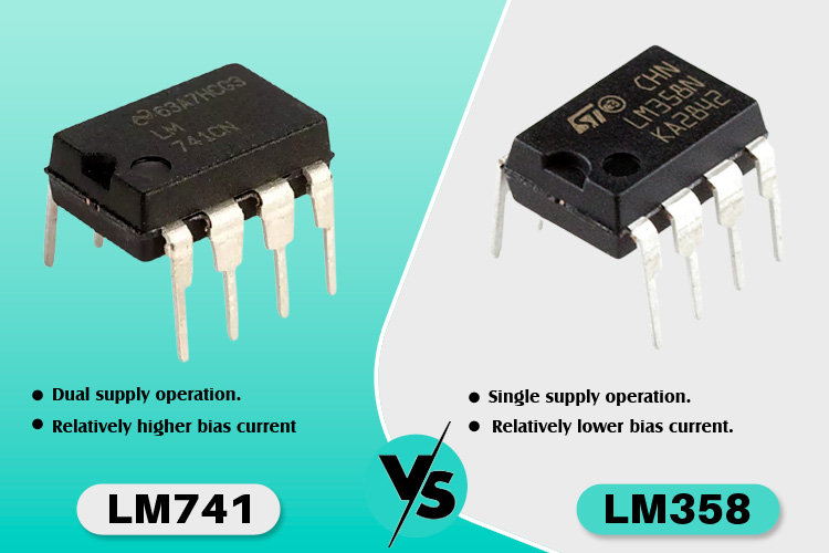
What is the difference between LM741 and LM358?
The LM741 and LM358 are both operational amplifier (op-amp) integrated circuits, but they have some key differences in terms of specifications, functionality, and application areas. Here are the main differences between the LM741 and LM358 op-amps:
LM741 Op-Amp:
-
General Purpose Op-Amp:
- The LM741 is a general-purpose op-amp with a single high-gain amplifier.
-
Performance:
- Higher input impedance and gain bandwidth product compared to the LM358.
-
Voltage Range:
- Typically operates with a higher power supply voltage range (commonly ±5V to ±18V).
-
Pin Configuration:
- Eight-pin DIP package with a different pinout compared to the LM358.
-
Applications:
- Suitable for applications requiring higher gain and bandwidth, such as instrumentation amplifiers, audio amplifiers, and signal conditioning circuits.
LM358 Op-Amp:
- Dual Op-Amp:
- The LM358 contains two operational amplifiers on a single chip.
- Low Power Consumption:
- Designed for low power consumption applications, making it suitable for battery-operated devices.
- Input Offset Voltage:
- Typically has lower input offset voltage compared to the LM741.
- Voltage Range:
- Operates with a lower power supply voltage range (commonly +3V to +32V).
- Pin Configuration:
- Eight-pin DIP or small outline integrated circuit (SOIC) package with a different pinout compared to the LM741.
- Applications:
- Ideal for low-power applications, voltage followers, low-frequency signal processing, and general-purpose operational amplifier tasks.
Comparison Summary:
- LM741 is a single op-amp with higher gain and bandwidth, suitable for applications requiring precision and high performance.
- LM358 is a dual op-amp with lower power consumption, designed for low-voltage, low-power applications and general-purpose tasks.
Considerations:
- Choose the LM741 for applications that require higher precision, bandwidth, and gain.
- Select the LM358 for low-power, lower voltage applications where dual op-amps are needed on a single chip.
When selecting between the LM741 and LM358 op-amps, consider the specific requirements of your circuit, such as power consumption, input/output voltage ranges, gain, bandwidth, and number of required op-amps on a single chip. It's essential to refer to the datasheets of both components to ensure they meet the necessary specifications for your application.